
Views: 0 Author: Site Editor Publish Time: 2026-08-12 Origin: Site


High-volume automotive manufacturing demands a rigid balance between rapid cycle times, strict weight reduction targets, and uncompromising structural integrity. Misunderstanding the physical limitations, metallurgical chemistry, and thermal dynamics of the die casting process leads to costly design revisions, premature tooling failure, unacceptable porosity rates, and delayed production launches. Moving beyond basic definitions, this guide breaks down the exact mechanics of automotive die casting. We examine the realities of material behavior under extreme pressure and the technical criteria required to evaluate manufacturing partners. You will learn how to mitigate production risks, manage thermal fatigue on hardened steel dies, and specify the correct secondary operations for tight tolerances. By understanding these core mechanical constraints, engineering teams can design components that survive the injection cycle and perform reliably in the field.
Automotive die casting relies on injecting molten alloys at extreme pressures (10–175 MPa) to achieve rapid solidification, making it viable only for high-volume production where tooling costs can be amortized.
Material selection and melt chemistry dictate process limits; aluminum offers the best strength-to-weight ratio for structural components, while zinc provides superior thin-wall capabilities and tool life.
Achieving tight tolerances often requires secondary operations; evaluating a supplier requires assessing their integrated CNC machining, automated casting cells, and quality validation (CMM, X-ray) capabilities.
Porosity is an inherent risk in high-pressure die casting (HPDC); successful procurement requires vetting a supplier’s vacuum casting capabilities, gating design expertise, and machine tonnage capacity.
To evaluate a supplier's capability to produce complex geometries, engineering teams must understand physical constraints. High-pressure injection cycles dictate specific machinery requirements. The interaction between molten metal and hardened steel dies defines the ultimate success of the production run. You cannot design a part without knowing how the machine physically forces metal into the cavity.
Cold-chamber and hot-chamber processes serve entirely different automotive applications. Aluminum requires cold-chamber systems due to its high melting point. The molten metal is ladled into a cold shot sleeve before injection. Zinc operates perfectly in hot-chamber machines where the injection mechanism sits submerged directly in the melt. Shot speed and pressure fill complex mold cavities before premature metal solidification occurs. The plunger must accelerate instantly to force metal through the gating system.
The injection cycle breaks down into three distinct phases. First, the slow shot phase pushes metal past the pour hole to prevent air entrapment. Second, the fast shot phase rams the metal into the cavity at speeds exceeding 40 meters per second. Finally, the intensification phase applies massive pressure to squeeze the solidifying metal, feeding shrinkage voids. Cycle time calculations directly impact production scalability. Faster cycles reduce the thermal load on the die surface. Automated ladling and extraction become necessary to maintain consistent cycle speeds. Variations in cycle time disrupt the thermal equilibrium of the mold, leading to dimensional drift.
Injection Phase | Plunger Speed | Primary Function | Risk if Improperly Set |
|---|---|---|---|
Slow Shot (Phase 1) | 0.1 - 0.5 m/s | Move metal past pour hole, gather melt | Severe air entrapment in the shot sleeve |
Fast Shot (Phase 2) | 2.0 - 8.0 m/s | Fill the cavity before metal freezes | Cold shuts, incomplete fill, flow marks |
Intensification (Phase 3) | Static (High Pressure) | Squeeze metal to feed shrinkage | Internal shrinkage porosity, weak structure |
Matching part size and projected area to press capacity ensures proper casting. Small brackets run efficiently on 400-ton machines. Massive structural nodes require 6000-ton giga-presses. The projected area of the casting dictates the required clamping force. Insufficient locking force leads to die separation during the intensification phase. This physical failure causes excessive flash along the parting line. It also creates severe dimensional inaccuracies and rejected parts.
Engineers calculate the injection pressure multiplied by the projected area to determine minimum tonnage. Safety factors are added to account for pressure spikes. Running a mold on an undersized machine guarantees premature tool wear and constant quality issues. You must verify that your manufacturing partner has the exact machine tonnage required for your specific component.
Machine Tonnage | Typical Automotive Application | Max Projected Area (Approx.) |
|---|---|---|
400 - 600 Tons | Sensor brackets, small pump housings | 100 - 150 sq. inches |
800 - 1200 Tons | Transmission covers, oil pans | 200 - 300 sq. inches |
1600 - 2500 Tons | Engine blocks, transmission cases | 400 - 600 sq. inches |
4000+ Tons (Giga-press) | Rear underbody structures, battery trays | 1000+ sq. inches |
Die temperature control systems maintain dimensional stability. Water and oil lines regulate cooling rates throughout the mold. Proper thermal management prevents localized hot spots that cause shrinkage voids. Melt quality and chemistry demand strict control on the foundry floor. Pre-injection degassing removes dissolved hydrogen from the liquid aluminum. Fluxing and dross removal prevent oxide inclusions in the final cast.
Hardened H13 steel dies experience severe thermal fatigue over time. This constant heating and cooling causes heat checking on the cavity surface. Heat checking leaves raised veins on the cast part. Understanding this wear mechanism dictates predictive maintenance schedules and insert replacements. If a supplier ignores thermal management, the die will fail prematurely, halting your production line.
Choosing the right alloy involves a strict trade-off. You balance mechanical properties, castability, part size, and tooling longevity. The selected metal dictates the required machine type and post-processing steps. You cannot force a high-strength alloy into a thin-walled geometry without expecting severe manufacturing defects.
Aluminum dominates the automotive sector for engine blocks and structural nodes. It delivers an exceptional strength-to-weight ratio and natural corrosion resistance. A380 serves as the industry standard for general automotive components. It offers excellent castability and pressure tightness. A356 provides higher ductility for critical suspension and chassis parts. However, aluminum has a high melting point. This characteristic causes aggressive wear on tooling compared to softer metals.
The molten aluminum actually solders to the steel die surface if release agents fail. Frequent die maintenance becomes mandatory when running high-volume aluminum components. Engineers must design parts with uniform wall thicknesses to prevent uneven cooling rates. Thick sections in an aluminum casting will inevitably draw molten metal from thinner sections, creating internal voids.
Magnesium drives extreme lightweighting initiatives across the automotive industry. Manufacturers use it for steering wheels, seat frames, and transfer case housings. Casting magnesium requires specialized safety protocols due to severe flammability risks. Cover gases like sulfur hexafluoride prevent the molten magnesium from oxidizing. Magnesium flows exceptionally well, allowing for thinner walls than aluminum.
Zinc offers superior castability for complex, small-to-medium thin-walled components. It causes minimal impact on die wear, allowing tools to last over a million shots. Engineers must balance zinc's precision against its higher density. Zinc components weigh significantly more than identical aluminum parts. This weight penalty limits zinc to smaller functional components like lock housings and sensor brackets.
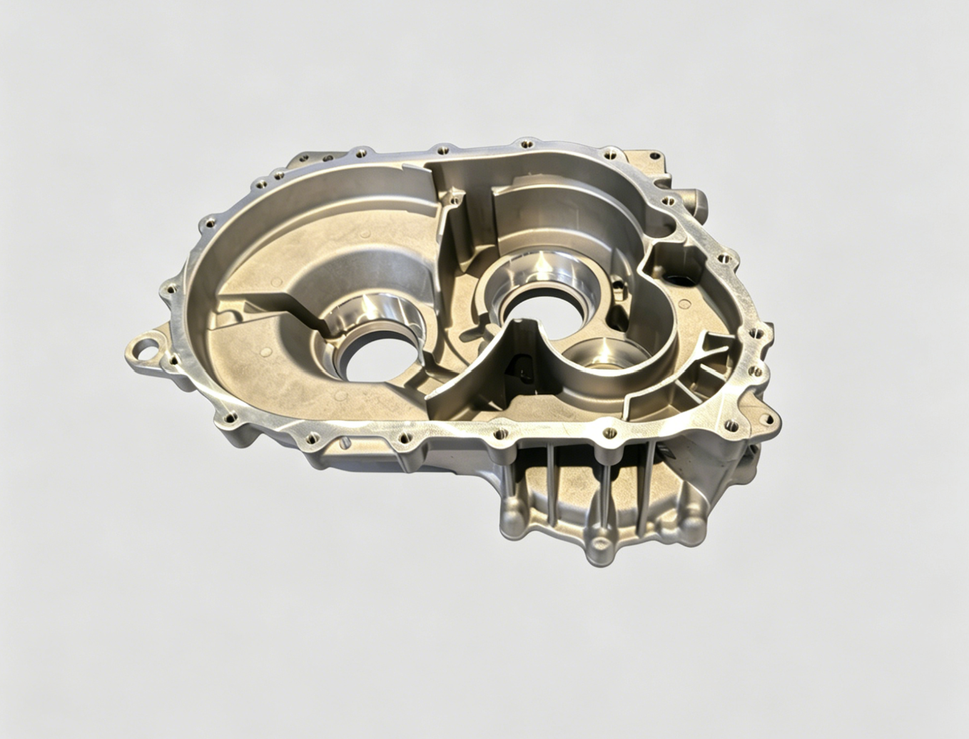
Raw castings rarely meet final automotive assembly tolerances immediately. They require secondary finishing, precision machining, and controlled post-processing. The casting process provides the near-net shape, while machining delivers the final exact dimensions. Relying solely on the as-cast tolerances for critical mating surfaces will result in assembly failures.
Secondary operations achieve the micro-tolerances required for transmission gear alignments. Bearing bores demand exact concentricity and strict perpendicularity. Producing CNC Machined Transmission Housing Castings requires advanced fixturing. Suppliers must index complex castings without inducing stress deformation. Tombstone fixtures on horizontal machining centers process multiple housings simultaneously. Structural integrity must remain intact during heavy material removal.
The machining setup for these housings follows a strict sequence to maintain datum references:
Establish the primary datum by milling the main mounting face flat.
Drill and ream locating pin holes to secure the casting for subsequent operations.
Rough bore the main bearing journals to remove the cast skin and relieve internal stress.
Perform finish boring operations using Polycrystalline Diamond (PCD) tooling to achieve tight concentricity.
Tap all mounting threads using roll taps to prevent chip contamination inside the housing.
Tool paths are optimized to prevent chatter on thin-walled sections. The transition from raw casting to finished housing requires seamless integration between the foundry and the machine shop.
Fluid-handling components carry strict pressure-tightness requirements. Design for Manufacturability (DFM) prevents leak paths and internal voids. An effective Automotive Engine Oil Pump Housing Die Casting avoids pressure drops. Engineers optimize wall thickness and gating to ensure solid material flow throughout the housing. The gerotor cavity demands exceptional flatness and surface finish.
Any porosity in the sealing areas leads to immediate fluid leaks. Vacuum-assisted casting often proves necessary to eliminate trapped gas in these thick-walled sections. Post-cast impregnation seals any micro-porosity before final assembly. During impregnation, the housings are placed in a vacuum chamber, and a specialized resin is drawn into the microscopic pores. The resin cures, rendering the casting completely pressure-tight.
Die surface finish directly impacts the final product. Automated release agent spraying and controlled injection speeds minimize surface defects. These controls prevent cold shuts, flow marks, and blistering. Delivering Smooth Surface Automotive Precision Castings involves specific post-processing realities. Shot blasting removes minor flash and creates a uniform matte texture.
Vibratory finishing smooths sharp edges and prepares the surface for coating. Plating prep meets cosmetic requirements without altering critical dimensions. Masking techniques protect machined sealing surfaces during abrasive blasting. The final surface roughness (Ra) dictates the success of subsequent gaskets and seals. If the surface is too rough, gaskets will fail to seal. If it is too smooth, certain adhesives may fail to bond properly.
Differentiating between a commodity casting shop and an automotive-grade partner matters. You need a manufacturer capable of repeatable precision. The right supplier integrates advanced technology with rigorous quality control systems. You must audit their facility to verify their technical claims.
Zero-porosity high-pressure die casting is a myth. The focus remains on controlled, non-critical porosity. Standard HPDC traps air inside the cavity during the high-speed injection phase. Vacuum-assisted die casting evacuates air from the cavity just milliseconds before injection. This process drastically reduces gas porosity in structural parts. It also enables necessary post-cast heat treatments.
Without a vacuum system, entrapped gas expands during heat treatment, causing surface blisters. Vacuum blocks and chill vents must be meticulously maintained to ensure proper air evacuation on every shot. The vacuum process follows a precise sequence:
The die closes and locks under full machine tonnage.
The vacuum valve opens, drawing air out of the cavity and shot sleeve.
The plunger advances, pushing molten metal into the evacuated mold.
The chill vent freezes the metal instantly, preventing it from entering the vacuum pump.
The part solidifies under high intensification pressure.
Robotics drive high-volume automotive runs. They ensure consistent ladling, die lubrication, and part extraction. Automation reduces cycle time variance significantly. It minimizes human error in thermal management and maintains steady production rhythms. End-of-arm tooling (EOAT) carefully removes hot castings without inducing distortion.
Automated trim presses shear off runners and overflows immediately after extraction. This continuous flow prevents bottlenecks on the foundry floor. A fully automated cell guarantees that shot number 10,000 matches the exact thermal profile of shot number 10. Manual operations introduce thermal fluctuations that ruin dimensional stability.
Hardened steel dies represent a significant upfront capital expenditure. This investment amortizes over a 100,000+ unit run. Evaluating supplier die maintenance programs ensures long-term success. Look for predictive maintenance schedules, expert weld repairs, and strategic insert replacements. Core pins wear out rapidly and require frequent swapping.
The die block itself must undergo stress-relieving treatments periodically. Proper lifecycle management prevents catastrophic tool failure mid-production. A dedicated tooling room within the casting facility indicates a supplier's commitment to uninterrupted production. They should have the capability to machine replacement inserts in-house to minimize downtime.
North American Die Casting Association (NADCA) standards guide precision tolerances. Apply these standards directly to automotive production requirements. NADCA distinguishes between Standard and Precision tolerances based on part geometry. In-house Coordinate Measuring Machines (CMM) verify exact dimensions. Real-time process monitoring ensures every batch meets stringent automotive specifications.
Statistical Process Control (SPC) tracks dimensional drift over time. This data allows engineers to adjust process parameters before parts fall out of tolerance. Relying on manual calipers is insufficient for modern automotive requirements. The supplier must provide detailed CMM reports mapping the critical datums of your component.
Common failure modes exist in automotive die casting. You must engineer them out during the DFM phase. Reactive problem-solving on the foundry floor wastes time and materials. Anticipate defects and design the tooling to prevent them.
Die separation under pressure causes flash. Manual trimming introduces variability, while automated trimming ensures consistency. Shrinkage occurs naturally as the molten metal solidifies and cools. Mold flow simulation software like MAGMASOFT predicts metal flow accurately. Engineers use this data during the design phase. They optimize gating systems and mitigate warpage risks before cutting steel.
Simulation identifies isolated heavy sections prone to shrinkage voids. Adding cooling lines or squeeze pins directly targets these problem areas. Proper draft angles prevent parts from sticking and warping during ejection. If a part lacks sufficient draft, the ejector pins will punch through the casting or warp it beyond repair.
Defect Type | Visual Appearance | Root Cause | Corrective Action |
|---|---|---|---|
Gas Porosity | Smooth, round internal voids | Air trapped during fast shot | Implement vacuum casting, adjust venting |
Shrinkage Porosity | Jagged, irregular internal voids | Isolated heavy sections cooling last | Add squeeze pins, redesign wall thickness |
Cold Shuts | Visible lines or cracks on surface | Metal freezing before cavity fills | Increase injection speed, raise die temp |
Soldering | Metal stuck to die, torn part surface | Inadequate die lube, hot spots | Adjust spray nozzles, increase water cooling |
Critical safety components mandate X-ray inspection and CT scanning. These methods detect hidden subsurface inclusions and excessive porosity. Establish clear Acceptable Quality Limits (AQL) early in the project. Define exactly what size and location of porosity is permissible. Finalize Production Part Approval Process (PPAP) requirements before launching mass production.
Material certifications must accompany every batch of alloy. Destructive testing, such as tensile pull tests, verifies the mechanical properties of the cast metal. A robust quality assurance program prevents defective castings from reaching the assembly line. The PPAP validation process requires strict adherence to documentation:
Design Records and Ballooned Drawings.
Process Flow Diagrams mapping the entire manufacturing route.
Process Failure Mode and Effects Analysis (PFMEA).
Control Plan detailing inspection frequencies and methods.
Measurement System Analysis (MSA) and Gage R&R studies.
Initial Process Capability Studies (Cpk).
Automotive die casting remains the most effective method for high-volume, complex metal part production. Success requires rigorous management of tooling investments, melt chemistry, and DFM processes. Precision machining and automated cells transform raw metal into critical automotive components.
Initiate a comprehensive DFM review with shortlisted manufacturing partners using mold flow simulation data.
Request documented tooling life guarantees based on specific alloy selections and predictive maintenance schedules.
Verify machine tonnage capabilities align perfectly with your part size, projected area, and required locking force.
Define strict porosity acceptance criteria and NDT requirements in your initial manufacturing specifications.
A: Tooling lifespan typically ranges from 50,000 to 100,000 shots. This variance depends heavily on part complexity, the specific aluminum alloy chosen, and the rigor of the die maintenance program. Aggressive alloys wear H13 steel faster, requiring predictive maintenance and insert replacements to maintain dimensional accuracy.
A: High-pressure die casting injects molten metal at extreme speeds and pressures (10–175 MPa). This allows for rapid cycle speeds and much thinner wall capabilities compared to gravity casting. While tooling costs are higher, the rapid production rate makes it ideal for high-volume automotive runs.
A: Machine tonnage refers to the clamping force applied to keep the die halves closed. Sufficient locking force prevents die separation under extreme injection pressures. This metric dictates the maximum projected area and size of the part that a specific machine can successfully cast without creating excessive flash.
A: Standard high-pressure die castings often blister during heat treatment due to entrapped gas expanding. To perform T6 heat treatments safely, manufacturers must use vacuum die casting systems. This evacuates air from the mold cavity before injection, minimizing gas porosity and preventing structural blistering.
A: Porosity primarily stems from gas entrapment during high-speed metal injection and poor melt degassing. Shrinkage during the rapid solidification process also creates internal voids. Proper gating design, vacuum assistance, and optimized thermal management help control and minimize these inherent defects.
A: While die casting produces near-net shapes, critical mating surfaces and bearing bores require tighter precision. Manufacturers rely on secondary CNC machining to achieve the exact micro-tolerances necessary for proper gear alignment, structural integrity, and fluid sealing in modern transmission housings.
A: Minimum wall thickness depends on the alloy and part geometry. Zinc components can achieve walls as thin as 1.0 mm. Aluminum structural parts typically require a minimum of 2.0 mm to 3.0 mm to ensure proper metal flow, prevent cold shuts, and maintain necessary structural integrity.


